
Views: 0 Author: Site Editor Publish Time: 2026-10-31 Origin: Site


Ever stared at a scattered box of mixed wire connectors, wondering which one to grab? I have spent years wiring complex industrial control panels and troubleshooting failed connections in the field. Making the wrong terminal selection is not just a minor inconvenience. Choosing an incompatible connector directly causes high-resistance joints, localized heating, electrical shorts, and even catastrophic fire hazards.
Let's break down the exact mechanical and operational differences between these essential components. We will dive deep into the classic debate of ring versus fork connectors. We will also clarify exactly where needle-like pin variants fit into your electrical schematics. By understanding these engineering nuances, you can confidently make the safest, most reliable choice for any wiring scenario.
Ring Terminals provide the most secure, vibration-resistant electrical connection available. However, they demand the complete removal of the mounting fastener during installation.
Fork Terminals enable rapid installation and modification without fully unscrewing the fastener. This makes them the optimal choice for frequently adjusted circuits.
Pin Terminals feature a solid, needle-like design. They are engineered specifically to consolidate stranded wires and fit seamlessly into tight, high-density spaces.
Selecting the correct component relies heavily on evaluating three primary variables. You must assess environmental vibration levels, spatial constraints within the panel, and the anticipated frequency of routine maintenance.
Before analyzing the specific geometry of different connectors, we need to establish a baseline. What are these components actually doing? What critical safety functions do they perform in modern electrical engineering?
At their core, high-quality insulated terminals are engineered electrical connectors designed to terminate stranded copper wire securely. They consist of a highly conductive metal barrel. In premium products, this barrel is crafted from tin-plated copper or brass to aggressively resist corrosion and ensure maximum conductivity. This metal core is then covered by a protective, non-conductive sleeve typically manufactured from flame-retardant Polyvinyl Chloride, Nylon, or specialized heat-shrink tubing.
For industrial applications, you want to look for components that carry robust specifications. A reliable terminal should offer a maximum voltage rating of around 600V and withstand operating temperatures up to 105°C. The primary function of this assembly is to facilitate a rock-solid mechanical and electrical bridge between a flexible wire and a rigid mounting point.
The non-conductive plastic sleeve on these connectors is far from merely cosmetic. It serves several fundamental safety purposes. Imagine opening a densely packed industrial control panel. In such tight quarters, exposed metal barrels can easily shift and touch adjacent terminals. This triggers immediate equipment failure. The insulation acts as a vital physical barrier against these accidental short circuits.
Furthermore, the insulation provides indispensable strain relief. When you crimp a wire, the transition point between the rigid metal barrel and the flexible copper wire becomes a severe stress riser. The insulated sleeve extends just past the metal core. It supports the wire jacket and drastically reduces the likelihood of delicate copper strands snapping under continuous flexing.
To standardize the industry and eliminate dangerous installation errors, wire connectors utilize a universal color-coding system. Adhering to these standards ensures that the copper strands fit snugly within the metal barrel. A snug fit is the foundational requirement for a structurally sound crimp.
Red Insulation: Engineered for wire sizes ranging from 22 to 16 AWG. These are typically deployed for low-current applications, precision sensor wiring, and small electronics.
Blue Insulation: Designed for 16 to 14 AWG. This represents the most common size for standard automotive harnesses, household appliances, and general control circuitry.
Yellow Insulation: Built for thicker 12 to 10 AWG wires. These handle higher current loads and are frequently found in heavy-duty machinery and power distribution blocks.
When absolute mechanical security and uninterrupted electrical continuity are your primary objectives, the enclosed loop design is the undisputed industry standard.
This component features a flat, circular metal contact area with a precisely machined hole in the center. The functional design requires the mounting screw or threaded stud to pass completely through this circular opening. Once the fastener is torqued down, the ring terminals are physically trapped between the screw head and the mounting surface. This 360-degree mechanical enclosure defines its operational superiority.
Attribute | Description |
|---|---|
Pros | Maximum Security: The captive design guarantees the wire cannot physically detach from the mounting point unless the fastener is entirely extracted. |
Pros | Vibration Resistance: Highly immune to mechanical loosening. Even if thermal cycling causes the screw to lose clamping force, the electrical connection remains intact. |
Cons | Slower Installation: Demands the complete removal of the mounting screw, adding tedious seconds or minutes to complex assembly processes. |
Cons | Maintenance Difficulty: In confined spaces where dropping a tiny screw into a machine is a real risk, the installation becomes significantly more stressful. |
Because of their inherent resistance to accidental detachment, these connectors are strictly mandated in environments characterized by constant movement or high mechanical resonance. Picture a marine engine room or an off-road vehicle chassis. In these scenarios, road shock and engine vibrations are relentless. They are also the go-to choice for permanent installations, such as main grounding points in commercial electrical panels.
While the enclosed loop offers peace of mind through absolute security, it is not always the most practical choice for fast-paced maintenance. This is where open-ended designs step in.
Widely recognized on job sites as a spade terminal, this component features an open-ended, U-shaped contact area. Instead of forcing a technician to pass a screw through a closed hole, the two parallel prongs slide smoothly directly under the head of a partially loosened screw or washer.
Attribute | Description |
|---|---|
Pros | Rapid Installation: Allows electricians to make secure connections by merely backing off a screw a few turns, sliding the metal prongs in, and retightening. |
Pros | Space Efficiency: If you have ever dropped a tiny mounting screw into the dark abyss of an engine bay, you understand the appeal of a slide-in connection. |
Cons | Lower Security: If the mounting screw vibrates loose, the open rear end allows the connector to slip right out. This instantly breaks the circuit. |
Cons | Not for High Vibration: Fundamentally unsuitable for environments where mechanical shaking is constant. The risk of catastrophic disconnection is simply too high. |
These units excel in static, climate-controlled environments where components are regularly serviced, tested, or upgraded. Rely on quality fork terminals for indoor industrial control boxes where relays, contactors, and timers are frequently swapped out. Additionally, they are perfect for diagnostic testing setups where rapid circuit modifications are a daily necessity.
Moving away from traditional screw-stud mounting systems, needle-like connectors serve a highly specialized but increasingly crucial role in modern, high-density electrical assemblies.
Unlike flat rings or open forks, a pin terminal is designed with a solid, cylindrical metal contact. Its primary architectural purpose is to consolidate the dozens of fine, fragile strands of a copper wire into one solid, rigid pin. This prevents the individual strands from splaying, fraying, or snapping when forced into deep compression-style receptacles.
Attribute | Description |
|---|---|
Pros | Prevents Wire Fraying: Completely eliminates the risk of stray copper strands protruding from a joint. This is a leading cause of arc flashes and cross-wiring shorts. |
Pros | Optimal for Compression: Provides a robust surface for set-screws or spring-cage clamps to bite into, ensuring a fierce mechanical hold without crushing wire strands. |
Cons | Incompatible with Studs: Cannot be utilized on traditional threaded posts or standard barrier strips. |
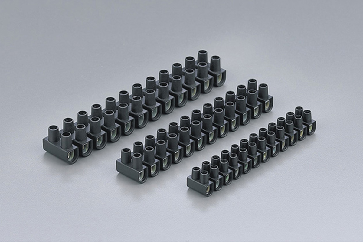
The application of these connectors is almost exclusively tied to insertion-based hardware. They are the mandatory companion for European-style terminal blocks, which utilize a tubular opening with a vertical set screw. Inserting bare stranded wire directly into these blocks often severs the strands. A solid pin provides the perfect interface. To achieve a flawless panel build, engineers frequently pair pin terminals with premium terminal block connectors featuring UL94V-0 flame-retardant housings to guarantee a standardized, secure fit in Programmable Logic Controllers.
When evaluating the fundamental differences in this classic debate, professionals must look beyond basic aesthetics. The decision ultimately rests on a careful evaluation of mechanical stability versus operational agility. Both connector types serve the identical function of terminating a wire to a stud, but their structural designs dictate entirely different performance outcomes.
The most prominent distinction between these two components lies in the delicate balance of mechanical security and convenience. Ring connectors offer a locked-in nature. Because the screw passes entirely through the barrel, the wire is physically trapped. Even if thermal expansion and contraction cause the fastener to lose its optimal torque over time, the terminal remains physically captive around the stud. It cannot pull away. This drastically reduces the risk of an arcing fault.
Conversely, the open-ended design prioritizes slide-in convenience. In complex control panels featuring dozens of contact points, the ability to bypass the complete removal of a fastener translates to massive labor savings. However, this convenience extracts a toll on security. If a screw backs out even a few millimeters, a slight tug or mere gravity can cause the open prongs to disengage completely.
The physical operating environment is the ultimate deciding factor. Vibration is the historic enemy of threaded electrical connections. In dynamic environments, constant low and high-frequency vibrations will inevitably cause standard screws to loosen. In these high-vibration scenarios, enclosed loops are the strictly mandated standard.
In contrast, static environments like a climate-controlled server room see virtually nonexistent vibration. In these highly controlled settings, the risk of a screw backing out autonomously is statistically negligible. This makes the operational convenience of an open-ended spade a highly practical and safe choice.
From my perspective in the field, the electrical manufacturing and panel-building sectors are undergoing a massive evolution. Space within control panels is at an absolute premium. Industrial machinery and automation systems are becoming increasingly compact. This spatial crunch has driven engineers away from bulky, traditional screw-stud layouts toward high-density, modular architectures.
Consequently, we are seeing a skyrocketing demand for specialized pin and ferrule terminals. Automated manufacturing facilities and renewable energy sectors heavily rely on spring-cage and push-in terminal blocks to save space and reduce wiring time. These advanced blocks require the solid, consolidated interface that only a needle-style connector can provide. This ensures delicate copper strands are not crushed during rapid assembly.
Furthermore, stringent modern safety regulations are pushing the industry toward foolproof, vibration-resistant connections. With the rapid rise of electric vehicles and mobile robotics, standardizing on premium, captive-loop connections for power distribution is no longer just a best practice. It is rapidly becoming a strict compliance requirement to prevent catastrophic field failures.
Selecting the correct component requires a systematic approach based on the specific parameters of your electrical project. Utilizing the wrong geometry leads to increased resistance and premature component failure. To streamline your decision-making process, refer to the following evaluation matrix.
Decision Criteria | Ring Terminals | Fork Terminals | Pin Terminals |
|---|---|---|---|
Primary Advantage | Maximum mechanical security and unmatched vibration resistance. | Rapid installation and effortless component swapping. | Fits flawlessly into high-density compression blocks. |
Vibration Tolerance | Extremely High | Low to Moderate | High (Depends heavily on the block mechanism) |
Installation Speed | Slow (Requires full fastener extraction) | Fast (Requires only loosening the screw) | Very Fast (Insert and clamp) |
Best Application | Automotive, marine, heavy motors, permanent wiring. | Control panels, relays, diagnostic circuits. | Captive screw connectors, PLCs, European blocks. |
Step-by-Step Selection Guide:
First, assess the equipment interface. Are you inserting the wire into a deep, tubular slot? You will need a solid pin to prevent strand fraying. Second, evaluate the vibration level. If the equipment shakes or generates internal mechanical resonance, default to an enclosed loop. Third, determine maintenance frequency. If the component is a consumable part requiring frequent replacement, open-ended spades will save you hours of cumulative maintenance time. Finally, always match the American Wire Gauge of your wire to the correct insulation color.
The reliability of an electrical circuit is only as robust as the crimp that secures it. Procuring professional-grade components is only the first step. Applying them correctly requires strict adherence to mechanical principles. A poorly executed crimp introduces high electrical resistance, generating localized heat that can eventually melt the plastic sleeve.
The most frequent, and often most dangerous, mistake made in electrical wiring is using standard flat pliers or cheap, stamped-metal tools. Pliers apply uneven, parallel force. They merely flatten the metal barrel into a pancake. This completely fails to create the necessary cold weld between the copper strands and the housing.
Professional installations absolutely require a ratcheting crimping tool equipped with dies specifically profiled for insulated sleeves. A ratcheting mechanism ensures that the tool will not release until a precise, factory-calibrated pressure has been applied. This guarantees a repeatable, uniform compression that tightly packs the copper strands together.
Proper wire preparation is the unsung hero of mechanical strength. The strip length must perfectly match the internal depth of the metal barrel.
If you strip the wire too short, the tool will blindly compress the metal barrel over the wire's original plastic jacket rather than the bare copper. This results in a weak grip and a dead circuit. Conversely, if stripped too long, bare copper strands will protrude awkwardly from the back of the sleeve. The bare copper should extend fully through the metal core, stopping just flush with the end. The wire's original jacket should sit securely inside the plastic sleeve to provide essential strain relief.
In professional panel building, non-destructive testing is standard operating procedure. Once a connector has been compressed onto a wire, it must undergo a manual tug test.
Grip the connector firmly in one hand and the wire in the other, then apply a steady, forceful pull. A properly cold-welded joint will easily withstand significant mechanical tension without the wire shifting inside the barrel. If the wire pulls out, the crimp has officially failed. Never attempt to re-crimp a failed joint. Cut it off, strip fresh wire, and start over with a new piece.
Choosing the right connector is the foundational step in ensuring long-term electrical safety and system reliability. By understanding the unique geometries of these components, you can eliminate guesswork and prevent hazardous field failures.
Remember, enclosed ring loops provide unshakeable, permanent connections ideal for high-vibration environments. Open-ended spades offer the operational agility needed for fast-paced maintenance. Meanwhile, solid pins are the undisputed champions of high-density, compression-style blocks.
Always match your hardware to the specific environmental demands of your project. Never compromise on the quality of your components or crimping tools. For a comprehensive range of premium, flame-retardant, and highly conductive wiring solutions, explore the professional-grade catalog at CHS Plastics to dramatically upgrade the safety and longevity of your next electrical build.
Yes, but this substitution is only advisable in highly controlled, static environments where the risk of the mounting screw vibrating loose is virtually nonexistent. In indoor control panels or temporary testing rigs, they provide excellent efficiency. However, for dynamic applications such as automotive, marine, or heavy industrial machinery, you should always stick to enclosed loops to ensure the connection remains physically captive.
PVC is the industry standard for general-purpose electrical work, offering a highly cost-effective solution with excellent dielectric strength. Nylon, however, is considered a premium, industrial-grade upgrade. Nylon is inherently more rugged, highly resistant to harsh petrochemical solvents, and much less prone to micro-cracking under extreme temperature fluctuations. Additionally, nylon sleeves are typically semi-translucent, allowing technicians to visually verify wire placement before crimping.
While they serve a similar purpose—consolidating stranded wire for insertion into terminal blocks—they are structurally different. A pin terminal features a solid, rigid metal needle attached to a crimp barrel. A wire ferrule is a thin, hollow copper tube that slides over the stripped wire strands and is then crimped into a square or hexagonal profile. Pin terminals are generally preferred for heavy-duty compression blocks, while ferrules are the standard for push-in and spring-cage European blocks.
You must strictly follow the universal color-coding system. Red terminals are for 22-16 AWG wires, blue terminals are for 16-14 AWG wires, and yellow terminals are for 12-10 AWG wires. Using a terminal that is too large for your wire will result in a loose crimp that can easily pull out or cause arcing. Using one that is too small will force you to cut away copper strands to make it fit, which dangerously reduces the current-carrying capacity of the circuit.
While standard ratcheting crimpers designed for insulated sleeves will technically function, they often flatten the base of the solid pin unnecessarily. To achieve optimal results and maintain the structural integrity of the needle shape, it is highly recommended to use a profile-specific crimping tool. Proper tooling ensures the barrel is compressed uniformly without distorting the pin, guaranteeing it fits perfectly into the precise tolerances of high-density blocks.

